Peavey PV-1200 Power Amplifier

peavey pv1200

First Impressions

I've never worked on a PV-1200 so I was approaching it with an open mind.

The first thing that struck me was the weight. It's heavy. That's a good sign. It points to a nice, big transformer.

On removing the top cover, I was met by the beast. Judging by the size and the weight, it's probably about 1kVA to 1.2kVA.

I couldn't help but notice that the PCB is inverted. Reminds me of the QSC 1700.


The Amplifier Module

I was horrified when I flipped the pcb over. I've never seen such small heatsinks in a high powered amplifier before. Mind you, this is not Class D.

I can only speculate that this must was an attempt at cost savings. As if to reinforce my suspicion, there are only four pairs of power transistors for the output. The two in the middle are actually the drivers.

peavey pv1200 pcb

What market is Peavey targetting

According to their manual, the PV-1200 is meant for Commercial and Industrial Installations as well as Studio and Home Use.

By commercial installations, I take it to be places where businesses are conducted, like a shopping mall. Now it's beginning to make some sense. Perhaps they were trying to compete with the likes of the vintage QSC Series. Those amps have a strong foothold in commercial installations like shopping malls, houses of worship, hotels & pubs.
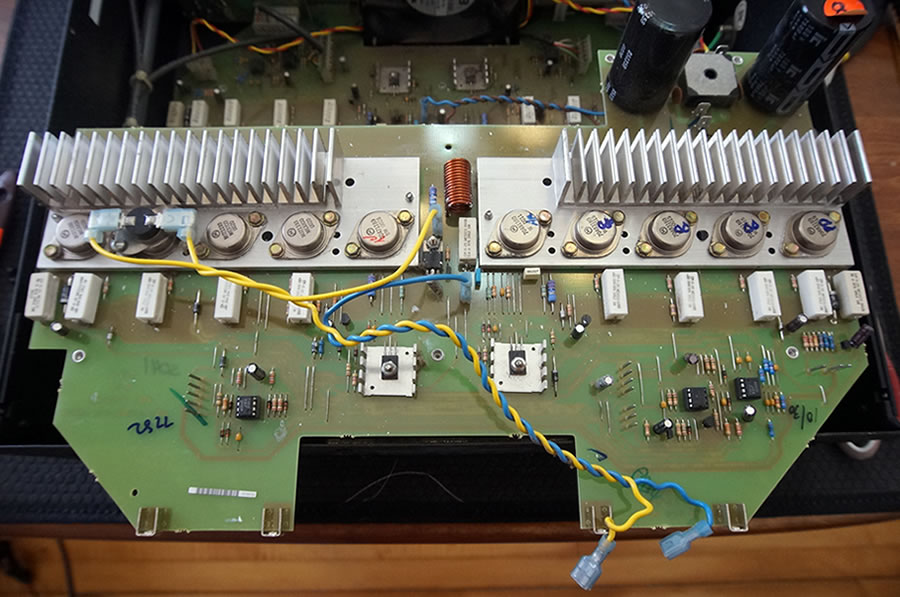
Such places will not be using power like those of a rock concert where amplifiers are pushed to their limits. Therefore, having massive heatsinks is just wasteful. And more importantly, it pushes the cost up.

In a highly competitive market, a cheaper product has an edge. Taken in that context, it's understandable for a manufacturer to scale down the heatsinks to reduce cost.

As for industrial, I believe that would be factories. I honestly have no idea what brands they use.

Regarding recording studios and home hifi, I seriously doubt amps for commercial installations are common. These two markets are extremely picky. Not just power amps. It's everything.


The Circuit

Let's take a closer look at how the PV-1200 works.
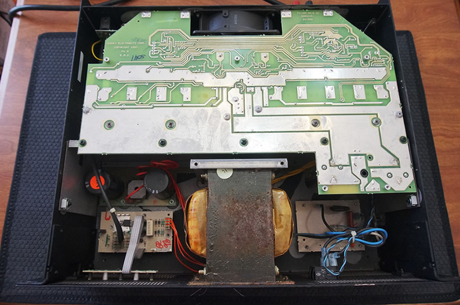
In conventional amplifiers, the speaker is connected to the output of the power transistors. In this design, we see that the emitters are grounded instead.

This would be fatal except that in this instance, the center of the two filter capacitors (7,500uF/100V) is not referenced to ground. In fact, it is "floating". And it is at this point the speaker is now connected to.

peavey pv1200 schematic

Voltage Amplification

If we study the circuit carefully, we see the opamp is driving the pre-drivers (Q104/105) directly. In other words, the entire voltage gain stage must come from the opamp.

Ordinarily, using an opamp to drive the outputs has severe limitations because the opamp cannot swing beyond the rail voltages (+/- 15Vdc). So how is it able to do that?

It has to do with a floating power supply. By grounding the emitters of the power transistors, their collector voltages will now swing when they are driven by drivers Q106/107.

It is not obvious in the schematic but the supply to the opamp is actually derived from the rail voltages of the power amplifier. So any voltage swing in the rails will be super-imposed onto the opamp. We can look at the opamp as being bootstrapped to the amplifier via the supply rails.

Bootstrapping the opamp and a floating power supply are what make this topology works. It was first introduced by QSC in the 80s, I believe. In the original version, the collectors are grounded.

Next > Repairing the PV-1200


60 Downes Street | Calais | ME 04619 | USA

weebly guest ipv6 traffic counter